Search This Blog

Thursday, 22 March 2012

Baking Ambient Occlusion map in Maya


                                   Baking ambient occlusion map in Maya

We are here to discuss about ambient occlusion map. If we want to give more details to our scene than ambient occlusion map can help us. Ambient occlusion map gives more depth to our scene. Baking ambient occlusion map is simple and easy. We are going to bake ambient occlusion map with the help of mental ray.

Step1: Create a model and unwrap it. When we are going to bake ambient occlusion map than we have to keep one thing in our mind is that overlapping of UV's is not allowed here. We have to avoid overlapping of UV's. If you don’t do this your A.O map will not be accurate.


Step 2: Now go to render settings and select mental ray. If mental ray is not showing in render settings than load it form plug in manager. For this go to windows and select plug in manager it will open a dialog box. Now choose Maya to mr.mll and click ok. Again go to render settings and choose mental ray as renderer.


Step 3: In rendering menu set go to windows than rendering option and select hyper shade. Choose surface shader here. Now click to texture under mental ray tab and select mib_amb_occlussion. In work area select mib_amb_occlussion texture and with the help of middle mouse drag and drop on to the surface shader and connect to default.


Step 4: Now apply this shader to the selected objects. It will make all the objects black coz surface shader has no color. Render the scene you will get some noisy image like this (image 3).

                                                                                  (1)
(2)

                                                                          (3)

Step 5: let’s see how our A.O map looks. For this we have to check the quality and adjust few settings. First adjust the sample rays to reduce the noise. Adjust the spread amount. This is the parameter from which you can control the width of your occlusion. normally at spread value of .75 is good. If you required than use max distance. No need to change this right now.


Step 6: Now we are ready to bake our A.O map. For this choose rendering menu set and under the lighting and texturing tab select batch bake mental ray. It will open a dialog box.


Step 7: In this dialog box just feed the details like objects to bake, bake shadow's, use bake set override, color mode, occlusion rays, prefix, file format and seam etc.


Step 8: click convert and close. A.O map is baked and save under the mental ray folder. To see A.O map go to project folder than metal ray and here go inside light map.


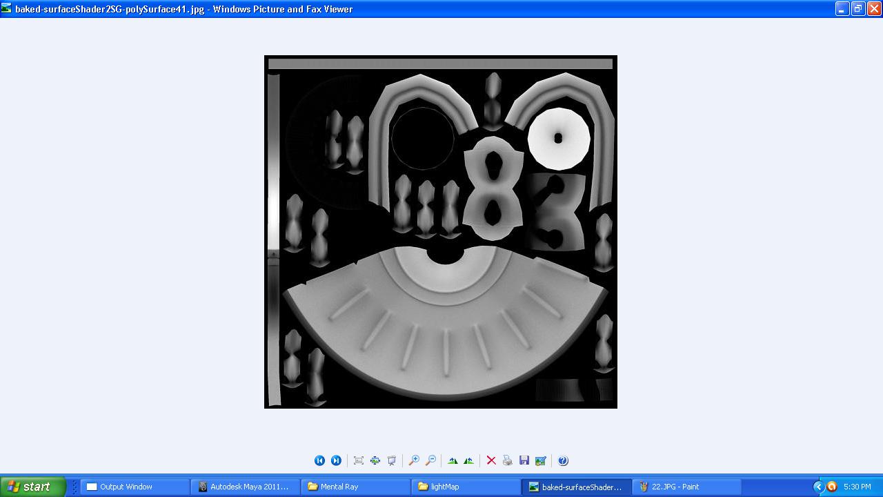
This is our baked A.O map

Step 9: Now we have to use our A.O. map. For this open this A.O map in Photoshop and place this layer on top of the color map in multiply mode. It’s very important to put this layer in multiply mode. Now you can see the depth in your color map. Apply this to your object and render.


                                               Left without using A.O and right side with A.O

Wednesday, 14 March 2012

How to create a new toolbar in 3ds-Max


How to create a new toolbar in 3ds-Max

Sometimes we want some commands to be seen in front of our eyes so that we can pick that commands quickly. We cannot create hot key for each and every tool or command. Than we have to look for other options. And other option is to create our own toolbar so that we can add commands according to our choice. Default toolbar is not set according to our choice. There are lots of commands which we use on regular basis but they are not in our default toolbar. For better workflow and speed we have to use both hotkeys and our own customize toolbar.

Step 1:-First go to customize option in menu bar and select customize user interface. It will open a dialog box. Here you can see lots of things to customize. You can create keyboard shortcuts, toolbars, menus, color etc. our aim is to create a new toolbar.


Step 2:-Select any toolbar and you will see the details related to it. You can see all available toolbars here. Click one by one and see different toolbars. We can create a new toolbar, delete an existing toolbar or rename a toolbar here. We are going to create a new toolbar.


Step 3:-Click on new it will create a new floating toolbar in viewport. Give a name to your new toolbar and click ok.


Step 4:-Now you can place your toolbar very easily in the interface. Just double click on it. When you double click on your new toolbar it will automatically place itself in the interface. If you want to place manually than click and hold with the left mouse button and place anywhere in main toolbar.

Step 5:-Now we are ready to add commands to our toolbar. For this we have to choose any group. For this again go to customize and select customize user interface.  Now here select any group like editable poly etc.

Step 6:- Here in action box choose the command which you want to add in your toolbar. Now just drag and drop in our toolbar. You can see commands in your toolbar. If you want to delete any command form your toolbar than just right click on that command button and click delete.
double click on your toolbar to see it  to see your toolbar

if you want to delete any command than just right and choose delete.


Saturday, 10 March 2012

UV sets in Maya

                                     U.V sets in Maya

Here we are going to discuss how to create different UV sets for an object. Why we need two or more UV sets for an object. When we are baking normal or ambient occlusion map then we avoid overlapping of UV’s. For this we required a different UV set.  But for better utilization of UV space we have to overlap UV’s. That’s why we need two or more UV sets.

Step 1:-Set project folder. object having UV set called map1.

Step 2:-Now we want another UV set for this object. For this we have to create empty UV set.
For this go to create UV's than choose create empty UV set. It will open a dialogue box.

Step 3:-Give name to new UV set.

Step 4:-Now go to UV editor and see your new UV set. Currently new UV set is empty.
 Select UV’S in UV editor.

Step 5:-Now select create UV’S and choose copy UVs to UV set. Select the new UV set.

Step 6:-Now go to UV editor and select new UV set. Now you can see this new UV set is having UVs now.

Step 7:-Do the required changes in your new UV set.

Step 8:-you can see the two different UV sets of object.

Step 9:- Just choose the required UV set to work.


Mesh cleanup


                                                         Mesh Cleanup

When we model an object in 3d software package like Maya few geometry problems left like Ngons (Faces with more than 4 sides), lamina faces, concave faces, Nonmanifold geometry etc. we have to clean our geometry before going to unwrap.
To remove this we have an option in Maya called cleanup. This option is available under mesh. Here we are going to clean our mesh one by one.

Step 1:-First of all we have few polygon models which we have to clean.

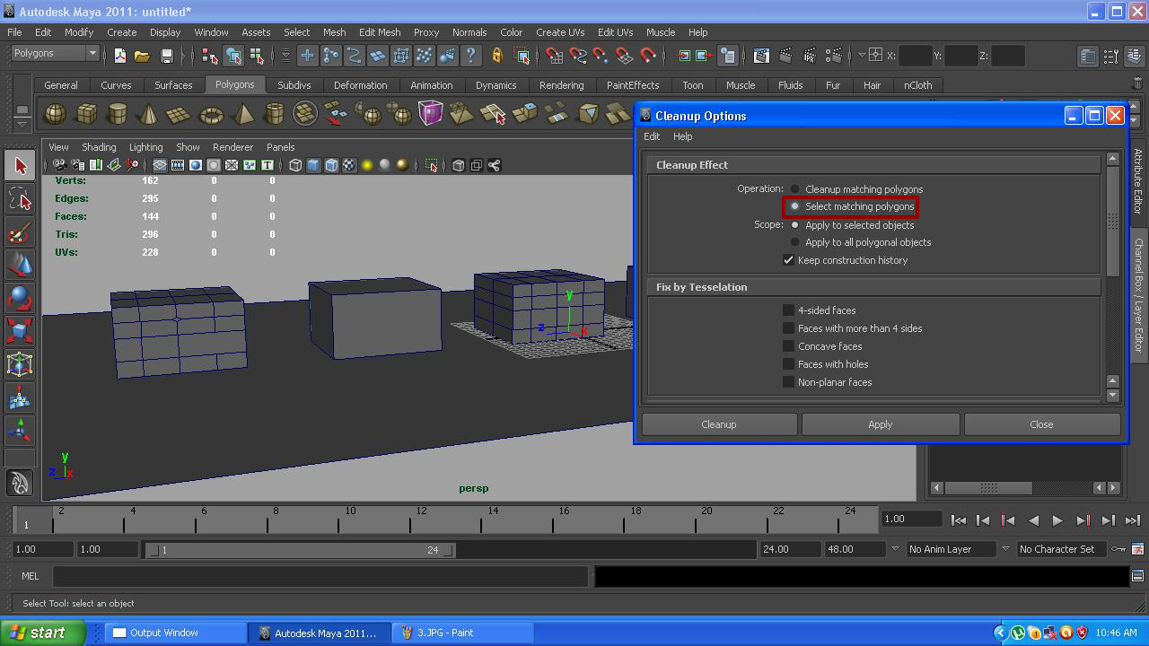
Step 2:-Go to mesh and select cleanup option form menu bar. It will open a dialogue box.

Step 3:-Now choose select matching polygons. It will only show where the cleanup is required.

Step 4:-If you want to see how many quads you have in geometry than select your mesh and choose --- 4-sided faces and click apply.
Step 5:-For Ngons (Faces with more than 4 sides) select your mesh and choose --- Faces with more than 4 sides and click apply. It will highlight those faces. Now we have to manually fix this.


Step 6:-When a polygon makes a shape of concave or you can say any corner of a polygon moves too much towards inside than this problem arise. Sometime we ignore this.


Step 7:-Choose faces with holes for those faces which contains holes. Select your mesh and choose ---- faces with holes and click apply.
Step 8:-Non planer faces are those faces which are not in a plan. Select your mesh and choose ---- Non planer faces and click apply.


Step 9:-Lamina faces are those faces which share all four edges. In other language two faces sharing same edges. Select your mesh and choose ---- Lamina faces and click apply. now delete the face.

Step 10:-Nonmanifold geometry means a polygon edge sharing 3 faces. Select your mesh and choose ---- Nonmanifold geometry and click apply.

Step 11:-Do this thing for all objects one by one or select apply to all polygonal objects.


That’s how we can clean our mesh.